Saturday, December 15, 2012

Front wheel bearing housing : part 3

The drilling and the tapping of the holes for the bolts to clamp the halves of each bearing housing together went like a dream.
First, holes of 5 mm were drilled in one half. With a transfer punch, the exact position for the holes in the other halve were being defined. The other half was drilled with 6.5 mm to allow a bit of play.
Finally, the holes of 5 mm were threaded with M6 thread.
Result:

This reminds me to make some more transfer punches in a dead moment. The one I used, I quickly fabricated from a piece of 5 mm diameter tool steel. I just turned a little point at the end with the lathe, but didn't harden it because I wanted to get on.
Using tool steel to make ones own tools is very satisfactory. After making with it whatever it is you want to make, you can easily harden it so it gets very durable.

Friday, December 14, 2012

Update on the front wheel rim

This week, I had the time and opportunity to visit the guy with the tube rolling machine in his workshop. A very friendly guy who understood what I needed. I gave him the specs for the front wheel and he promised it would be ready by next week Friday!! Cost for the rolled tube would be around 130€.
So speaking about good news!

Front wheel bearing housing : part 2

At last! Friday night again!

A few hours in my workshop and this is the result:


The two bearing housings start to look how they should look like. After cutting the flanges from a 12x12mm bar (top) and welding them to the bearing housing halfs, there was still some work to be done with the files as can be seen in the picture.
Next, the holes will be drilled, tapped and the flanges will be cut even (I left about 5 mm extra material to be cut off later).

Saturday, December 1, 2012

cutting thread in the front wheel hubs

This week I managed to tap all 60 holes in the two hubs:

I used the drill press as a way of keeping the thread cutting steady. I operated the belt of the drill by hand since the RPM of the drill would be too high when running on power.
My big fear was that the threadcutter would break, but everything went well. It's only aluminium after all.

As to my fear the tensile strength of the aluminium would not be sufficient, I did a little calculation with a spoke tension of say 100 kg.
Imagine the finished wheel with a spoke in the middle.
The middle spoke would be able to support 100 kg
The two spokes to the left and right would be able to support 100 * cos(360/60) = 99.45 kg each
The two spokes left and right of the previous ones would be able to support 100 * cos(360/60*2) = 97.81 kg each
...

Total load for one half of the wheel would be able to support approximately 2500 kg, so that should not be of any concern.

Monday, November 19, 2012

Steering pin

This week will be a very busy week, so I won't have the time I would like to have to spend working on the bike.
I finished the steering pin today:

 The steering pin mounted in the steering housing:


CAD drawing:

Friday, November 16, 2012

Big wheel

The most crucial part of a penny farthing bicycle is the front wheel.
A logical technical solution to produce a front wheel rim yourself is to start out with a tube which is rolled in a circle and welded together at the ends.
Since I don't have this equipment at home, I contacted someone who knows a guy with this kind of machinery. This person I contacted had experience with building his own recumbent bike and he suggested I make the rim out of stainless steel due to its mechanical properties. Since I was going to make the spokes out of stainless and the hub out of aluminium, this should present no significant problems as to alloy combinations. You should never combine normal steel with stainless, because this will cause corrosion because of the galvanic difference.
Rim construction will hopefully be done next week and will cost about 150€. Once I have the rim, I can start looking for the appropriate tire, calculate the exact fork size, etc.
The rim size has been calculated at 140cm diameter or roughly 54 inch.

CAD drawings

I experienced it is a good idea to make a CAD drawing of a project before execution because it makes you discover flaws in your thinking process.
I started the project with making a rudimentary drawing of the complete bike and I am bit for bit making separate drawings of the different parts and see how they fit together. I will try to find a way to post these so you can download them for own use.
As an example, I'm posting a link to the front wheel bearing housing .dxf file. Right click and 'save target as'.
front_wheel_bearing_housing


Thursday, November 15, 2012

Front Wheel Hubs

The front wheel hubs are made out of aluminium. The 30 hole pattern was made on a press drill. As you can see, I had to make some help-tooling to do this job. The hub is rotating on a piece of round steel which is mounted on the base plate which has been inclined to a 85 degree angle. This angle corresponds with the angle of the spokes with reference to the front wheel axle.
I hope the tensile strength of the aluminium will be sufficient when putting tension on the spokes. The holes are about 30mm deep and will be tapped with M3 thread.

Front Wheel Bearing Housing

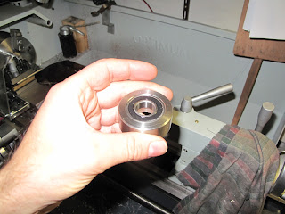
The front bearing housing is made out of tool steel and turned to fit the bearing. It will be cut in half later on so the bearing can be clamped between the halves.
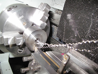
 On the lathe, an inside step is made so the bearing will be encased by the housing. After passing on the lathe, the bearing house looks like this:
 The bearing fits snugly, but there is no force needed. When the housing will be cut in half, flanges will be added so the bearing can be held firmly in the housing.


Steering assembly

I made the steering part out of standard gas tubing and profiles. The parts have just been spot-welded together and will be finished later on during final fork assembly.
The part just below the bolt/nut assembly is a piece of tool-steel which has been turned in a taper and tapped with adequate thread. The part in the bottom of the tube is also a piece of tool-steel.


Penny farthing building blog

I'll try to keep a diary of the building process of my own penny farthing bicycle.
The goal is to have it ready by spring 2013 so I can take it out of the workshop on a nice and sunny day and take it for a ride in Bruges.

I was inspired to build this bike by several other bike builders all over the world. I based the design of my bicycle on pictures of vintage examples on the internet and data from other bike builders sites.
I will try to use material that is readily available to me. The local shop has a selection of steel tubes and profiles which I will be using.
My workshop is not that big: apart from a lathe, I have a press drill, a welder and some standard hand tools like angle grinder, files,...

Please feel free to leave comments or questions. Since I don't have any previous experience with bike-building, it would be great to get some tips or simply hear from you...